
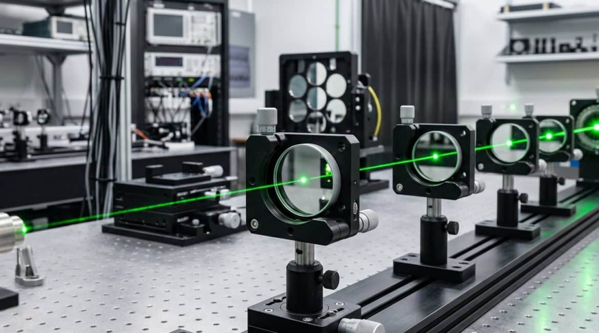
In precision laser processing equipment, such as laser cutting, welding, or marking machines, the laser beam emitted from the laser source must pass through a series of reflector mirrors. This precise relay ensures the beam accurately reaches the processing head and workpiece.
Imagine the laser source as a skilled marksman. The reflector mirrors in the beam path system are like the sights on his rifle. Even if the initial reflector mirror deviates by a mere thousandth of a degree, after several meters of transmission, the final laser spot could miss its target by several millimeters. This perfectly illustrates the saying, “A miss is as good as a mile.”
So, when the laser beam deviates, how do engineers “straighten” its path? Furthermore, how do they ensure this high precision remains stable over the long term?
I. Reflector Mirrors: The “Steering Wheel” of Beam Path Transmission
In Flying Optics systems, the laser source typically remains stationary. The laser beam redirects and transmits along the X, Y, and Z axes via a series of reflector mirrors.
The primary role of a reflector mirror is not just to change the beam’s propagation direction (usually a 90-degree reflection). Crucially, it also determines the incident position and angle when the beam finally reaches the focusing lens.
If the beam fails to strike the geometric center of the reflector mirror, or if its incident angle deviates, it leads to severe problems. For example, the end spot may deform (e.g., a circular spot becomes elliptical). Additionally, focusing energy significantly attenuates. The processing kerf might tilt, or it could even directly burn the nozzle and mirror box inside the cutting head, causing equipment damage.
II. Three-Point Alignment: The Core Technique for Precision Beam Path Calibration
To ensure the laser beam remains “straight” over long transmission distances, engineers commonly employ the “Three-Point Alignment” method. This technique uses an alignment plate or a red light indicator.
These “three points” refer to critical positions in the beam path:
- Starting Point: The laser emission source or the preceding reflector mirror.
- Near Alignment Point: The initial segment of the optical axis, close to the current reflector mirror.
- Far Alignment Point: The terminal segment of the optical axis, where the laser transmission distance is longest.
- Positioning with “Red Light” and Alignment Paper
Many high-power industrial lasers (e.g., 1064nm fiber lasers or 10.6µm CO2 lasers) are invisible to the naked eye. Therefore, the first step in beam path alignment often involves activating a co-axial red light indicator (a visible red laser). Alternatively, engineers place special indentation paper or alignment paper in front of the reflector mirror mount. This allows observation of the laser spot. - Near-Point Alignment: Adjusting “Position”
First, move the processing axis to the position closest to the current reflector mirror (the “near point”). Fire a low-energy laser pulse. Observe the spot’s exact location on the reflector mirror or target plate. Then, adjust the translation screws of the preceding mirror mount. This ensures the spot precisely hits the geometric center of the current reflector mirror. - Far-Point Alignment: Adjusting “Angle”
Next, move the processing axis to the furthest end (the “far point”). Fire the laser again. At this point, the spot will likely deviate from the center. This typically happens because the angle of the preceding reflector mirror has a slight tilt. Importantly, in this step, do not move the mirror mount’s position. Instead, adjust the three fine-tuning screws on the back of the mirror mount. These control the elevation and azimuth angles of the reflector mirror. This brings the far-point spot back to the center. - Iterative Verification and “Coincidence”
Adjusting the reflector mirror angle slightly affects the near-point spot’s position. Consequently, engineers must repeatedly move the processing axis back and forth between the near and far points. They repeat the “adjust position at near point, adjust angle at far point” procedure. This iterative process continues until the laser spot perfectly coincides at the same center point at both the near and far ends. This completes the coaxial alignment of the reflector mirror.
III. Mechanical Structure Stability: A “Protective Wall” Against Vibration and Thermal Deformation
A common problem arises: why does a perfectly aligned beam path deviate after some time? This often stems not from the alignment technique itself, but from vulnerabilities in mechanical structure stability.
Here are the main reasons for beam path instability:
- Micro-stresses from Thermal Expansion and Contraction: High-power laser transmission causes the reflector mirror mounts and bases to absorb small amounts of heat. If the mirror mount material is uneven, thermal expansion leads to micron-level deformation. This, in turn, pulls the beam off course.
- Workshop Vibration and Loosening of Fasteners: During laser equipment operation, high-frequency vibrations occur. For instance, motors start and stop rapidly, or robotic arms move back and forth. If adjustment screws lack high-precision locking rings or anti-loosening mechanisms, prolonged micro-vibrations can cause slight screw thread slippage. This alters the reflector mirror’s position or angle.
- Insufficient Rigidity and Cantilever Sag: For long-travel optical axis systems, a lack of high-rigidity aluminum profiles or steel structural support is problematic. As the gantry moves to the far end, gravitational settling (or “cantilever sag”) changes the physical attitude of the reflector mirror. This causes the beam path to deviate.
Therefore, a high-quality laser system requires reflector mirror mounts with high-rigidity structures. They must use premium materials with low thermal expansion coefficients (e.g., stainless steel or special alloys). Furthermore, they need double-nut locking mechanisms or precision anti-loosening devices. These features effectively resist temperature changes and mechanical vibration interference, ensuring long-term beam path stability.
Expert Maintenance Recommendations
- Clean First, Align Second: Before performing any beam path alignment, always thoroughly inspect the reflector mirror surface. Check for dust, oil stains, or other contaminants. Dirt not only interferes with alignment paper readings but also absorbs laser energy, generating intense heat. This severely impacts alignment accuracy and can even cause failure.
- Gradual Fine-Tuning: When adjusting the fine-tuning screws on the back of the reflector mirror, always proceed with “small, slow adjustments.” Avoid large rotations. Even a tiny adjustment, such as an eighth of a turn of a screw, can cause significant displacement of the far-end spot.
- Establish a Fixed-Point Verification Mechanism: We recommend that equipment maintenance personnel regularly (e.g., weekly) perform a red light target spot verification at the furthest end of the machine’s processing area. By maintaining a beam path drift log, they can timely detect and record changes in the beam path trend. This helps eliminate potential hidden dangers before they result in scrapped workpieces.