
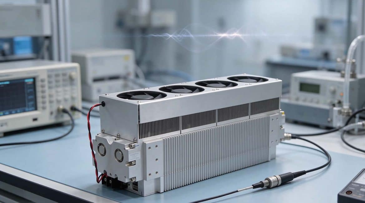
The RF laser tube serves fine marking, high-speed engraving, and precision thin-film cutting lines. It offers fast response and excellent beam quality.
However, many engineers and maintenance staff meet a common problem in daily production. The RF laser tube output power starts to jump after some runtime. It becomes strong one moment and weak the next. As a result, some products fail to cut through, some burn, and some show uneven engraving lines.
Unlike a standard glass-tube laser, the RF laser tube does not reveal its condition through discharge color alone. Its interior combines high-frequency circuits, impedance matching, and a precise cavity. Therefore, do not dismantle the RF laser tube blindly when power becomes unstable. Instead, check three core areas in order: the RF signal source, the matching network, and the resonant cavity.
- Direction One: RF Signal Source (Power and Control End)
The RF signal source acts as the energy supply center of the RF laser tube. It converts DC power into high-frequency RF energy at tens of megahertz, such as 40.68MHz or 81.36MHz. If this source becomes unstable, RF laser tube output power will shake strongly.
Common Faults
First, excessive ripple in the 24V/48V DC power supply can disturb the RF laser tube. Aging capacitors in this DC supply may modulate the high-frequency RF signal with low-frequency ripple. That modulation appears as periodic power fluctuation in the RF laser tube.
Second, interference on the PWM modulation signal can destabilize the RF laser tube. If the pulse-width modulation line lacks shielding, it can pick up strong electrical noise. Running this line parallel to high-power cables can also shift modulation frequency and duty cycle. These changes affect RF laser tube output stability.
Third, overheating in the RF power amplifier MOSFET can reduce RF laser tube efficiency. A failed fan or dried thermal paste raises the MOSFET temperature quickly. The device then protects itself and lowers RF laser tube power.
Detection and Adjustment Steps
First, measure the DC input of the RF power supply with a multimeter or oscilloscope. Check whether voltage drop exceeds 5% at full RF laser tube output. Also inspect the waveform for clear low-frequency ripple.
Second, measure the input of the RF driver board with an oscilloscope. Confirm the PWM square wave amplitude, usually 5V, and check its frequency and duty cycle. Verify that the signal edges do not show strong spike interference. This check helps confirm stable control of the RF laser tube.
Third, check the amplifier area temperature with an infrared thermometer. If temperature rises above 80°C within a few minutes, clean the cooling duct at once. Replace the thermal paste if needed, because heat threatens the RF laser tube.
- Direction Two: Matching Network (Impedance Matching System)
The RF generator must match the plasma impedance of the discharge cavity, usually 50 ohms. The matching network bridges the RF source and the RF laser tube cavity. When matching fails, RF energy cannot enter the gas effectively. It becomes reflected power and returns toward the RF source. This reflected power can cut RF laser tube output sharply. It can also create intense heat and damage the amplifier MOSFET.
Common Faults
First, thermal drift in matching capacitors can upset the RF laser tube. High-power, high-frequency capacitors may shift capacitance slightly after heating. That shift breaks the matching state and reduces RF laser tube performance.
Second, arcing or cold solder joints can change impedance suddenly. In high-frequency, high-voltage conditions, coil and capacitor contacts may oxidize. They may develop cold solder joints or spark over. These faults create sudden impedance changes inside the RF laser tube.
Detection and Adjustment Steps
First, monitor forward power and reflected power with a professional RF power meter, such as a Bird vector power meter. Connect it between the RF source and cavity. A healthy RF laser tube shows reflected power below 5% of forward power. If reflected power exceeds 15%, matching is seriously unbalanced.
Second, disconnect power and open the matching box cover. Inspect capacitor and inductor contacts for blackening, burning, or cracked solder joints.
Third, fine-tune the variable matching capacitor with an insulated adjustment rod. Do this under professional RF monitoring and reduce reflected power to the lowest point. Never turn capacitor screws blindly without measuring instruments. This rule protects the RF laser tube and the technician.
- Direction Three: Resonant Cavity and Gas State (Optical Path and Cavity)
After RF energy enters the cavity, the gas produces photons and amplifies them back and forth. The RF laser tube output can become unstable if the cavity or gas changes.
Common Faults
First, cooling system temperature control failure can destabilize the RF laser tube. The RF laser tube is highly sensitive to temperature. Each 1°C change in cooling water can expand the metal cavity by microns. This expansion changes mirror distance and angle, so output power rises and falls. Therefore, temperature stability directly affects RF laser tube performance.
Second, thermal lensing or contamination on mirrors can distort the beam. Oil or dust on the full-reflection mirror or output coupling mirror absorbs laser energy. The mirror then heats, deforms, and distorts the RF laser tube beam spot. This distortion reduces power and changes spot shape.
Third, a small gas leak or slow gas aging can weaken discharge uniformity. A sealed metal cavity may develop a tiny leak, and air may enter. The RF laser tube then discharges unevenly, and power decays after startup.
Detection and Adjustment Steps
First, verify cooling accuracy. Check the chiller or air-cooled heat sink performance. The chiller should hold ±0.5°C at minimum, and ±0.1°C is better. Check whether RF laser tube power fluctuation follows the compressor cycle.
Second, check mirrors and the beam spot. Fire a test spot on burn paper at the RF laser tube output. A healthy spot should be a clean single-mode circle. If the spot turns oval or ring-shaped over time, thermal deformation or misalignment may exist.
Third, assess gas tightness and gas aging. Rule out power, matching, and temperature issues first. If cold-start power is normal but RF laser tube power keeps fading after ten minutes, gas may have degraded. Abnormal discharge color supports this diagnosis. Then contact the manufacturer for vacuum pumping and gas refill service.
Expert Maintenance Summary
When RF laser tube power becomes unstable, remember one logical order: outside first, inside second; electrical first, optical second.
First, check DC power and control signals at the RF source. Second, measure reflected power and contact condition in the matching network. Finally, verify water temperature, water quality, and beam spot shape in the resonant cavity. Follow these steps to remove external interference first. This approach improves troubleshooting efficiency and reduces unnecessary downtime. Moreover, it protects the RF laser tube from unnecessary damage.