In the CO2 laser world, beam transmission resembles a precise relay race. If the “baton” (laser beam) misses the next “runner” (a laser mirror), energy loss occurs. Furthermore, the beam might “derail,” potentially burning the optical frame. Therefore, accurate laser mirror path alignment is a machine’s lifeline. It ensures efficient operation and extends component lifespan.
Why is Precise Alignment Paramount?
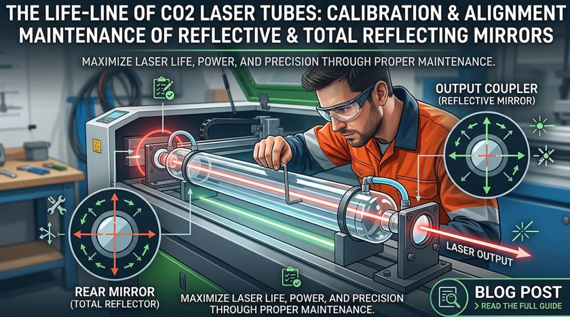
CO2 laser beams are invisible infrared light (10.6μm wavelength). Many operators believe light output is sufficient. However, this is incorrect. The precision of laser mirror path alignment directly impacts several key areas:
- Maximize Efficiency: The laser beam must strike the laser mirror’s center. This ensures minimal energy loss after reflection. Consequently, it maintains a high-quality fundamental mode (TEM00). This also guarantees optimal processing efficiency and quality.
- Prevent Thermal Distortion: A beam deviating from the center hits the laser mirror mount edge. This generates significant heat. Such heat causes mount deformation. Subsequently, this deformation further shifts the laser path. This creates a difficult-to-correct vicious cycle.
- Protect Expensive Components: Long-term off-center strikes cause carbon buildup or uneven heating on the laser mirror edge. This significantly shortens the lifespan of total reflector laser mirrors and output coupler laser mirrors.
Essential Calibration Tools: Preparation is Key
Before starting calibration, gather these necessary tools:
- Beam Alignment Paper (Thermal Paper/Double-Sided Tape): This serves as the most intuitive “target” tool. It shows the laser spot’s position and shape.
- Power Meter (Optional, but Highly Recommended): It quantifies power changes before and after calibration. This provides objective data to assess calibration effectiveness.
- Specialized Hex Wrench: Use it to adjust the three knobs behind each laser mirror mount. This precisely controls the laser mirror’s angle.
Professional Calibration Process: The “Targeting Method” (Step-by-Step)
Here are the detailed steps for laser mirror path alignment using the “targeting method”:
Step 1: Intracavity Alignment of Total Reflector and Output Coupler
This task occurs during laser tube manufacturing or deep maintenance. The total reflector laser mirror and the output coupler laser mirror must remain highly parallel. If the laser spot is not perfectly round, intracavity alignment issues are likely. However, for general users, maintenance primarily focuses on external laser mirrors.
Step 2: First Laser Mirror Calibration
Place beam alignment paper in front of the first laser mirror. Briefly press the “pulse” button to fire the laser. Observe if the spot falls precisely on the laser mirror’s center. If it is off-center, adjust the laser tube’s position by translating it. Do not adjust the laser mirror mount angle.
Step 3: Coincidence of Near and Far Points (The Most Crucial Step)
First, pull the moving gantry to its nearest position. Fire a laser pulse, creating a spot on the beam alignment paper. Next, push the gantry to its furthest position. Fire another laser pulse, making a second spot on the same paper.
- Evaluation and Adjustment: If both near and far spots perfectly coincide, the laser path is parallel to the guide rail. If the spots diverge, adjust the three knobs behind the preceding laser mirror mount. Continue until both spots perfectly overlap. This step ensures stable laser mirror path transmission.
Step 4: Vertical Downward Calibration
The laser beam must pass vertically through the focusing lens center after entering the cutting head. Subsequently, it must exit the nozzle center. If the beam enters the nozzle at an angle, it will not cut through effectively. Furthermore, severe dross will appear on one side of the cut kerf. This significantly impacts processing quality.
Power Meter Method: Data Doesn’t Lie
After completing the “targeting method” calibration, use a power meter for final validation.
- Measure Initial Power: Take one laser power reading at the laser tube’s exit.
- Measure Final Power: Take another laser power reading at the cutting head nozzle.
- Professional Standard: Laser mirror path transmission loss should remain under 10%. If loss is excessive, unseen scattering or laser mirror contamination likely exists within the laser path. Further investigation is necessary.
Preventive Maintenance Suggestions
To maintain optimal laser performance and extend its service life, follow these preventive maintenance suggestions:
- Regularly Check Screws: Machine vibrations can loosen mounting screws. Therefore, check the laser mirror path alignment points weekly. Ensure all laser mirrors are securely positioned.
- Clean Before Calibrating: Dust on a laser mirror can cause “sparks” during alignment. These sparks can directly burn the coating layer. This leads to irreversible damage. Consequently, ensure all laser mirror surfaces are impeccably clean before any calibration.
- Mind Environmental Temperature Differences: For large laser systems, temperature fluctuations (e.g., seasonal changes) can cause thermal expansion and contraction of the machine frame. This may slightly shift the laser mirror path. Therefore, re-adjustment is required to maintain precision.